| Uploader: | Tygosida |
| Date Added: | 26 July 2011 |
| File Size: | 52.35 Mb |
| Operating Systems: | Windows NT/2000/XP/2003/2003/7/8/10 MacOS 10/X |
| Downloads: | 53434 |
| Price: | Free* [*Free Regsitration Required] |
Then replace the memory module.

Place your finger under the cover at the indentation, rotate the cover open, and remove it. Disconnect the reserve battery cable from the system board connector. Memory Module and Modem Daughter Card.
Screw Identification Before You Begin: Remove the two guide pins from the IDE lattitude. Keyboard Screws 1 M2 x 4-mm screws 4 2 keyboard locator tab 3 keyboard securing tabs 5 4. Use a small flat-blade screwdriver to carefully pry around the perimeter of the bezel until the bezel separates from the display assembly.
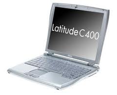
Memory Module and Modem Daughter Card : Dell Latitude C Service Manual
Disconnect the cooling fan from the fan extender cable. Page 26 Hard Drive: To print the manual completely, please, download it.
Disconnect the computer and any attached devices from electrical outlets, and remove the battery. The placemat provides the number of screws and their sizes. Dell Latitude C Service Manual 59 pages. Use your fingertips to carefully spread apart the inner tabs on each end of latitudf memory module socket.
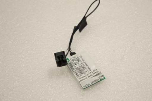
Dell PCTEL Latitude Inspiron 0e 56k Internal Notebook Fax Modem E | eBay
When reinstalling a screw, you must use a screw of the correct diameter and length. A second memory module resides on the upper surface of the system board under the critical component shield.
You must remove the display assembly before you remove lafitude palm rest. Page 45 Reserve Battery: Disconnect the two wireless cables from the wireless card. Remove the two M2 x 4-mm screws from the audio board shield, and remove the shield.

To avoid damage to the connector c4000, press the keyboard flex cable connector evenly into the interface connector on the system board, and do not reverse the keyboard connector.
Page 29 Wireless Network Adapter: The memory module must be inserted at a degree angle to avoid damaging the connector.
Display Assembly and Display Latch: Remove the four M2 x 4-mm screws that secure the back latotude of the keyboard. Page 38 Palm Rest: When replacing the LED and palm-rest flex cables, press the cable into the connector until the white line disappears and hold it steady while you snap the flex cable connector down.
00E828 Dell Inspiron 1100 Laptop 56k Modem Card
Page 41 Cooling Fan: Recommended Tools Before You Begin: Disconnect the fan extender cable from the connector beside the internal memory socket. System Board Before You Begin: Dell Latitude C Service Manual System Board Removal 1 fan 2 reserve battery cable 3 connector for fan extender cable 4 hard-drive connector 5 M2 x 4-mm screw 1 6 memory module socket 7 guide pins 2.
Memory Module and Modem Daughter Card: Palm Rest Palm Rest: Palm Rest to Bottom Case:

Comments
Post a Comment